- 您现在的位置:买卖IC网 > Sheet目录868 > LTM8008HV#PBF (Linear Technology)IC DC/DC UMODULE 16-LGA
�� �
�
�LTM8008�
�APPLICATIONS� INFORMATION�
�T� SS� =� C� SS� ?�
�SSpin,initiatingasoft-startoperation.Thesoft-startin-�
�terval� is� set� by� the� soft-start� capacitor� selection� according�
�to� the� equation:�
�1.25V�
�10μA�
�Thermal� Lockout�
�If� LTM8008� internal� temperature� reaches� 165°C� (typical),�
�the� part� will� go� into� thermal� lockout.� The� power� switch�
�will� be� turned� off.� A� soft-start� operation� will� be� triggered.�
�The� part� will� be� enabled� again� when� the� die� temperature�
�has� dropped� by� 5°C� (nominal).�
�Loop� Compensation�
�Loop� compensation� determines� the� stability� and� transient�
�performance.� The� LTM8008� uses� current� mode� control� to�
�regulate� the� output� which� simplifies� loop� compensation.�
�The� optimum� values� depend� on� the� converter� topology,� the�
�component� values� and� the� operating� conditions� (including�
�the� input� voltage,� load� current,� etc.).� To� compensate� the�
�feedback� loop� of� the� LTM8008,� a� series� resistor-capacitor�
�network� is� usually� connected� from� the� V� C� pin� to� GND.�
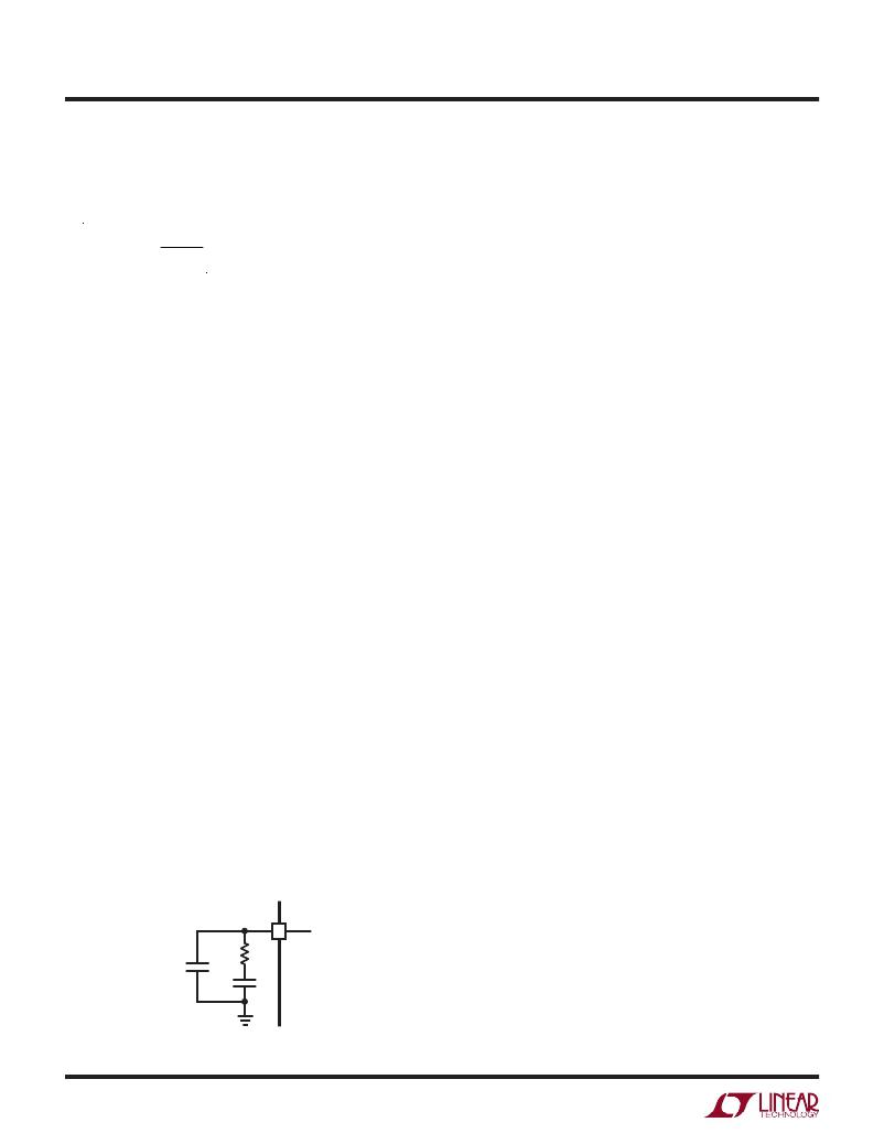
�Figure� 2� shows� the� typical� V� C� compensation� network.� For�
�most� applications,� the� capacitor� C� C1� should� be� in� the� range�
�of� 1nF� to� 47nF,� and� the� resistor� R� C� should� be� in� the� range�
�of� 2.5k� to� 50k.� A� small� capacitor� C� C2� is� often� connected� in�
�parallel� with� the� R� C� compensation� network� to� attenuate� the�
�V� C� voltage� ripple� induced� from� the� output� voltage� ripple�
�through� the� internal� error� amplifier.� The� parallel� capacitor�
�usually� ranges� in� value� from� 10pF� to� 100pF.� A� practical�
�approach� to� design� the� compensation� network� is� to� start�
�with� one� of� the� circuits� in� this� data� sheet� that� is� similar�
�to� your� application,� and� tune� the� compensation� network�
�to� optimize� the� performance.� Stability� should� then� be�
�V� C�
�R� C�
�C� C2�
�C� C1�
�8008� F02�
�checked� across� all� operating� conditions,� including� load�
�current,� input� voltage� and� temperature.�
�Board� Layout�
�The� high� speed� operation� of� the� LTM8008� demands� careful�
�attention� to� board� layout� and� component� placement.� The�
�GND� pads� of� the� package� are� the� primary� heat� path� of� the�
�device,� and� are� important� for� thermal� management.� There-�
�fore,� it� is� crucial� to� achieve� a� good� electrical� and� thermal�
�contact� between� the� GND� pads� and� the� ground� plane� of�
�the� board.� For� the� LTM8008� to� deliver� its� full� output� power,�
�it� is� imperative� that� a� good� thermal� path� be� provided� to�
�dissipate� the� heat� generated� within� the� package.�
�It� is� recommended� that� multiple� vias� in� the� printed� circuit�
�board� be� used� to� conduct� heat� away� from� the� LTM8008�
�and� into� a� copper� plane� with� as� much� area� as� possible.� To�
�prevent� radiation� and� high� frequency� resonance� problems,�
�proper� layout� of� the� components� connected� to� the� LTM8008�
�is� essential,� especially� the� power� paths� with� higher� di/dt.� The�
�high� di/dt� loop� should� be� kept� as� tight� as� possible� to� reduce�
�inductive� ringing.� In� the� SEPIC� configuration,� the� high�
�di/dt� loop� contains� the� power� MOSFET,� sense� resistor,�
�output� capacitor,� Schottky� diode� and� the� coupling� capacitor.�
�Keep� the� circuit� path� among� these� components� as� short�
�as� possible.�
�The� LTM8008� is� a� switching� power� supply,� so� care� must�
�be� taken� to� minimize� EMI� and� ensure� proper� operation.�
�Even� with� the� high� level� of� integration,� you� may� fail� to�
�achieve� specified� operation� with� a� haphazard� or� poor�
�layout.� See� Figure� 3� for� a� suggested� layout.� Ensure� that�
�the� grounding� and� heat-sinking� are� acceptable.� Here� are�
�additional� tips� to� follow:�
�1.� Place� the� L1,� R� T� and� V� C� components� as� close� as� pos-�
�sible� to� their� respective� pins.�
�2.� Place� the� C� IN� ,� C� INTVCC� ,� SPV� and� C� OUT� capacitors� as� close�
�as� possible� to� their� respective� pins.� If� more� than� one�
�capacitor� is� required� in� parallel,� place� as� many� of� the�
�electrically� paralleled� capacitors� as� close� as� possible�
�to� their� respective� pin.�
�3.� Place� the� C� IN� and� C� OUT� capacitors� such� that� their� ground�
�currents� follow� a� path� as� short� as� possible.�
�Figure� 2.� A� Typical� Compensation� Network�
�8008fa�
�10�
�发布紧急采购,3分钟左右您将得到回复。
相关PDF资料
LTM8020IV#PBF
IC DC/DC UMODULE 200MA 21-LGA
LTM8023MPV#PBF
IC BUCK SYNC ADJ 2A 50LGA
LTM8025MPV#PBF
IC CONVERTER BUCK 3A ADJ 70LGA
LTM8026MPV#PBF
IC UMODULE 36VIN 5A CVCC 81LGA
LTM8027EV#PBF
IC BUCK SYNC ADJ 4A 113LGA
LTM8032MPY#PBF
IC DC/DC UMODULE 2A 71BGA
LTM8033MPV#PBF
IC DC-DC UMODULE BUCK 3A 76-LGA
LTM8040IV#PBF
IC LED DRVR HP CONST CURR 66-LGA
相关代理商/技术参数
LTM8008HVPBF
制造商:LINER 制造商全称:Linear Technology 功能描述:72VIN, 6 Output DC/DC SEPIC μModule Regulator
LTM8020
制造商:LINER 制造商全称:Linear Technology 功能描述:Low VIN, 8A DC/DC μModule Regulator
LTM8020EV#PBF
功能描述:IC DC/DC UMODULE 200MA 21-LGA RoHS:是 类别:电源 - 板载 >> DC DC Converters 系列:µModule® 设计资源:VI-200, VI-J00 Design Guide, Appl Manual 标准包装:1 系列:* 类型:隔离 输出数:1 电压 - 输入(最小):55V 电压 - 输入(最大):100V Voltage - Output 1:5.8V Voltage - Output 2:- Voltage - Output 3:- 电流 - 输出(最大):* 电源(瓦) - 制造商系列:100W 电压 - 隔离:* 特点:* 安装类型:通孔 封装/外壳:9 针半砖 BusMod 尺寸/尺寸:2.36" L x 2.28" W x 1.08" H(59.9mm x 57.9mm x 27.4mm) 包装:散装 工作温度:-25°C ~ 100°C 效率:* 电源(瓦特)- 最大:*
LTM8020EV#PBF
制造商:Linear Technology 功能描述:DC/DC Converter IC
LTM8020EVPBF
制造商:Linear Technology 功能描述:DC to DC Step Down Power Supply
LTM8020EV-PBF
制造商:LINER 制造商全称:Linear Technology 功能描述:200mA, 36V DC/DC μModule
LTM8020IV#PBF
功能描述:IC DC/DC UMODULE 200MA 21-LGA RoHS:是 类别:电源 - 板载 >> DC DC Converters 系列:µModule® 设计资源:VI-200, VI-J00 Design Guide, Appl Manual 标准包装:1 系列:* 类型:隔离 输出数:1 电压 - 输入(最小):55V 电压 - 输入(最大):100V Voltage - Output 1:5.8V Voltage - Output 2:- Voltage - Output 3:- 电流 - 输出(最大):* 电源(瓦) - 制造商系列:100W 电压 - 隔离:* 特点:* 安装类型:通孔 封装/外壳:9 针半砖 BusMod 尺寸/尺寸:2.36" L x 2.28" W x 1.08" H(59.9mm x 57.9mm x 27.4mm) 包装:散装 工作温度:-25°C ~ 100°C 效率:* 电源(瓦特)- 最大:*
LTM8020IV#PBF
制造商:Linear Technology 功能描述:DC/DC Controller LTC 制造商:Linear Technology 功能描述:IC, DC/DC MOD REGULATOR, 450kHz, LGA-21